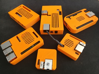
Collecting ARM development boards has become a disease I've been carrying for a while now. Welcoming a new board to the family is always filled with hope for a better future. But the ARM support in Linux being what it is, only deception, anger, and betrayal remain. Making use of the new board soon becomes a distant dream, and it ends up with the other devilkins in a forgotten corner of my desk.
Nevertheless, I felt the need to design and 3D print individual coffins for them. This led me into a long and painful OpenSCAD adventure resulting in the birth of the ShimonBox project.
The ShimonBox project
Quoting the GitHub page:
ShimonBox is an OpenSCAD project aiming at providing semi-automatically generated 3D printable cases for development boards.
The name comes from Simon "The Digger" in Tengen Toppa Gurren
Lagann. The dude is drilling like a madman, which is basically
the concept I'm using in ShimonBox.

Let me elaborate on this. The project is split in 3 main parts:
- the boards
- the electronic components of the boards
- the cases
The boards .scad files mainly define the plate and components dimensions,
their size, and positions. From this, we can basically generate a bounding box
drilling far in some direction. This is what it typically looks like (in red):
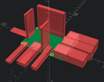
Since the boards' .scad files also define a 2D shape of the plate, it can be
vertically extruded into a large block which is then mined
by that bounding box to fit the board. This is the main principle I use to get
a generic case layout following the board design.
You may also notice the bounding box is actually including a padding and a smoothing (thanks to minkowski()) to have a safer and cleaner case.
The boards
The board definitions contain most of the information required to design a case. This means that if you want to build your own case, you can still use ShimonBox. For example, with the Cubieboard you can do something like:
use <shimonbox/boards/cubieboard.scad>
cubieboard();
You can also use the cubieboard_plate_2d() module and obtain the board
information by calling cubieboard_info(). Oh, and you will find
bounding_box() in utils.scad.
While this could be considered completely irrelevant to the problem the project is supposed to solve, I tried to make the board designs look pretty and close to how they appear in reality in order to get a neat semi professional output.
The GIF animations are obtained by generating 300 high resolution images using
openscad with a fixed camera position, and then running a 2-pass
FFmpeg on them to obtain a 4x downscaled output. That manual
multi-sampling technique gives a relatively good anti-aliased result. The
openscad calls can be run in parallel thanks to GNU/Make. The curious can
have a look to /common.mk for the details.
But what matters is what defines a board in the project. A typical board
.scad file contains the following:
- A bunch of includes for all the required electronics models
- The plate holes configuration (position, diameter, ring)
- The components bounding box dimensions (see next section why)
- A
<board>_plate_2d()module to get the 2D design of the plate; some plates such as the BeagleBone Black do not have symmetric corners and require a custom layout - An array of all the components, their orientations, and positions on the plate (see next section for details); this is the most important thing as it is used to generate the bounding box
- A main module named after the board name, used to obtain the design itself which must be consistent with the component definitions declared above; it is not used at all for the case modeling, it is meant to provide the prettified design of the board
- The exposed function
<board>_info()to export all information of the board outside, typically used to generate the case - A "demo"
moduleso the file is usable inopenscad
This may look like a long list, but the files are actually small. Some information on the other hand may look relatively redundant; this is due to the language limitations of OpenSCAD. While I tried my best to prevent it, at some point you have to deal with two completely incompatible models: the modules versus the functions, for which you have to create a bridge. I'll expand on that in a later section.
The electronics
The electronic components is the database of all the electronic
components you can find on the boards. This is currently a bit messy since I
had to switch the basis of a vector space several times during development. To
save time, I had to stack translate() and rotate() on top of them instead
of adjusting the whole code of all the components. Some cleanup is required,
but the result is consistent.
Something you may wonder about is "why do you have to specify a bounding box dimension for every component in your board definition?". That's a legitimate concern; after all, components like USB slots are typically all the same, that's standardized. Well, not really. In practice, the length of the slot itself varies, sometimes the tip has no folding, the thickness may actually be different... And this is true for basically all electronics. So for every board, you will actually have to measure again all your components.
Beside the parametric model of the component, there is one important setting:
the direction it is facing: horizon, sky or nowhere. This will define
the drilling direction.
The positioning of the component on the board can be overwhelming because it relies on several parameters:
- the component corner reference
- its rotation
- the border corner reference
- the actual position
The position is a vector going from the component corner reference to the border corner reference. The rotation will use the component corner reference as anchor.
The two corners references are integer vec3 where each axis is either 0
(center), or -1 or 1 (negative or positive corner). The rotation vec3
are also made of integers between 0 and 3 (for 0, 90, 180 or 270°
rotate).
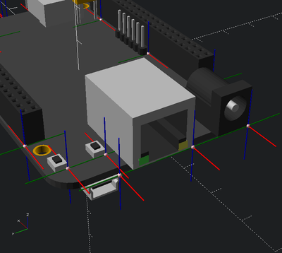
To help not getting lost in space while reconstructing the board,
set_components() has an extra debug option to show up the component corner
reference:
The case
When the board is defined, there is really not much left to do. The case
.scad files only contains 2 pieces of information:
- The arbitrary vent positions and dimensions
- The minimum and maximum on the z-axis; this is arbitrary because just like the vents, there are many possible solutions
If you look at a typical case definition, the file is a few lines
of glue code. But if you open it within openscad, you will get a full
featured case split in 2 or 3 parts (depending on the need for button pushers
or not).
All the logic happens in the /case.scad file. It's not actually a lot of code (less that 300 lines currently).
Some lessons with OpenSCAD
Working on a complex project with OpenSCAD for a few months gave me a large overview of the software, so I feel like sharing some feedback on it.
The good
Let's be honest, OpenSCAD is a solid piece of software (I can't remember a single crash), the syntax is very clean and simple, and its parametric nature is priceless. The native live editing with your own editor is also extremely handy. The preview is fast enough, and overall the experience was pretty intuitive all along.
The community is also extremely supportive, and I'll have to thank in
particular teepee and InPhase from IRC for their valuable help. Oh, and
they even added me to the official OpenSCAD gallery. Great
people ;)
OpenSCAD is also as far as I know the only free software that could achieve what I did with ShimonBox.
The bad
Now of course, my toxic hater nature cannot be silenced so easily, so I'll share a few critics.
- First, the language is actually too simple. The structures are pretty
limited. You want a string to function hash mapping? Well, do it yourself
with lists of lists and
search()calls (seemap_get()in ShimonBox). You want to do the same with modules? Good luck. You can somehow hack something with a custom filter (look forfilter()in ShimonBox). But really, this is the reason ShimonBox can be so redundant with regard to structures, and you have to do implicit mappings all around (that is, maintaining two separate lists for the same thing). - There is also no control over symbols visibility, which is a problem if you provide a library. At least, contrary to the free-for-all language that Python is, the variables are not exported, you have to write a function to expose them. Still, it's not possible to officially make local functions and modules.
- The language could benefit from little improvements, such as supporting
syntax like
x,y,z=vecwherevecis an array. - I mentioned the live coding earlier, but it's a bit buggy when following includes (typically, editing a board will not always reload the preview of the case).
- The rendering is insanely slow, don't try it with ShimonBox. Fortunately, I didn't need it much.
- The lack of recent release makes me sad too... A lot of work has been done since 2015, it's a shame no one benefits from it.
- Preview shaders could be improved, typically the wired output (
Ctrl-1) could get some love for a more professional output. - Animation module is kind of limited, please at least put a progress bar in the UI, it's currently unusable.
What's next
I'll probably continue melting PLA for various other boards I have (the two previous RaspberryPi generations and an Odroid C2). I'll write some documentation and tutorial as soon as I can on how to contribute easily (this blog post is a good start though). And maybe the incredible popularity of this project will give some people the irresistible urge to send me new boards so I can add them in the collection.